Channel EQ Parameters
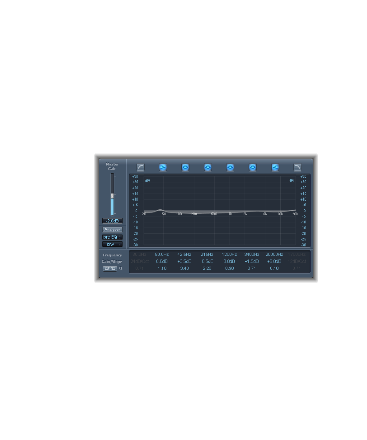
The left side of the Channel EQ window features the Gain and Analyzer controls. The
central area of the window includes the graphic display and parameters for shaping each
EQ band.
Channel EQ Gain and Analyzer Controls
• Master Gain slider and field: Sets the overall output level of the signal. Use it after
boosting or cutting individual frequency bands.
• Analyzer button: Turns the Analyzer on or off.
• Pre/Post EQ button: Determines whether the Analyzer shows the frequency curve before
or after EQ is applied, when Analyzer mode is active.
• Resolution pop-up menu: Sets the sample resolution for the Analyzer, with the following
menu items: low (1024 points), medium (2048 points), and high (4096 points).
Channel EQ Graphic Display Section
• Band On/Off buttons: Click to turn the corresponding band on or off. Each button icon
indicates the filter type:
53
Chapter 3
Equalizers

Band 1 is a highpass filter.
Band 2 is a low shelving filter.
Bands 3 through 6 are parametric bell filters.
Band 7 is a high shelving filter.
Band 8 is a lowpass filter.
• Graphic display: Shows the current curve of each EQ band.
• Drag horizontally in the section of the display that encompasses each band to adjust
the frequency of the band.
• Drag vertically in the section of the display that encompasses each band to adjust
the gain of each band (except bands 1 and 8). The display reflects your changes
immediately.
• Drag the pivot point in each band to adjust the Q factor. Q is shown beside the cursor
when it is moved over a pivot point.
Channel EQ Parameter Section
• Frequency fields: Adjust the frequency of each band.
• Gain/Slope fields: Set the amount of gain for each band. For bands 1 and 8, this changes
the slope of the filter.
• Q fields: Adjust the Q factor or resonance for each band—the range of frequencies
around the center frequency that are affected.
Note: The Q parameter of Band 1 and Band 8 has no effect when the slope is set to
6 dB/Oct. When the Q parameter is set to an extremely high value, such as 100, these
filters affect only a very narrow frequency band and can be used as notch filters.
• Link button: Activates Gain-Q coupling, which automatically adjusts the Q (bandwidth)
when you raise or lower the gain on any EQ band, to preserve the perceived bandwidth
of the bell curve.
• Analyzer Mode buttons (Extended Parameters area): Choose Peak or RMS.
• Analyzer Decay slider and field (Extended Parameters area): Adjust the decay rate (in dB
per second) of the Analyzer curve (peak decay in Peak mode or an averaged decay in
RMS mode).
• Gain-Q Couple Strength pop-up menu (Extended Parameters area): Choose the amount
of Gain-Q coupling.
• Choose “strong” to preserve most of the perceived bandwidth.
• Choose “light” or “medium” to allow some change as you raise or lower the gain.
• The asymmetric settings feature a stronger coupling for negative gain values than
for positive values, so the perceived bandwidth is more closely preserved when you
cut, rather than boost, gain.
54
Chapter 3
Equalizers

Note: If you play back automation of the Q parameter with a different Gain-Q Couple
setting, the actual Q values will be different than when the automation was recorded.